well, I can imagine mixing the powder with a soluble termobinding and print things literally in cocaine. Then when they arrive to destination, you dissolve the binding (or not, the extra plastic may give flavor or something), dry and grind the resulting paste, and profit.
6 Likes
I can’t evaluate whether this would actually work from a technical standpoint - but it certainly makes for a fantastic plot device in a story!
7 Likes
Yeah, i won’t elaborate more because I don’t want to start doing what I do in these cases (investigate the feasibility of something that I have no need of) but what I know is there are already cases of mixing cocaine with plaster and making plasterboards out of it. The plaster can be later -mostly- separated by dissolution. There was news of police “busting” a container full of “plasterboards”.
But I already feel my ADD brain wanting to do more research SO I WILL STOP HERE AND NOW - See brain? I can be in charge too!
8 Likes
Well, that was the plot of “License to Kill”, only they dissolved the cocaine in gasoline. ![]()
6 Likes
Be careful - mixing cocaine with other things doesn’t always go smoothly, I’m told.
, sampled film, 2018.")
ETA: Here’s to you, @Bonivus_elderheart !

6 Likes
JINX! :: grabs two cold frosty beverages from the fridge, hands one to Murgatroyd ::
5 Likes

Changing theme, I saw this new printer that seems to check all my boxes (except multimaterial support, but for now I can live without that), the Qidi Plus 4. Similar price range as bambulab offers, but bigger print area, open source toolchain and higher temperatures that allow for printing technical materials.
")
Now I just need to find the money ![]()
6 Likes
Working on making a little robot guy for a team-building event at work. I did something similar once before on a slightly larger scale but this time I’m using smaller servos and it’s challenging to package enough of them to get all the functions I want.
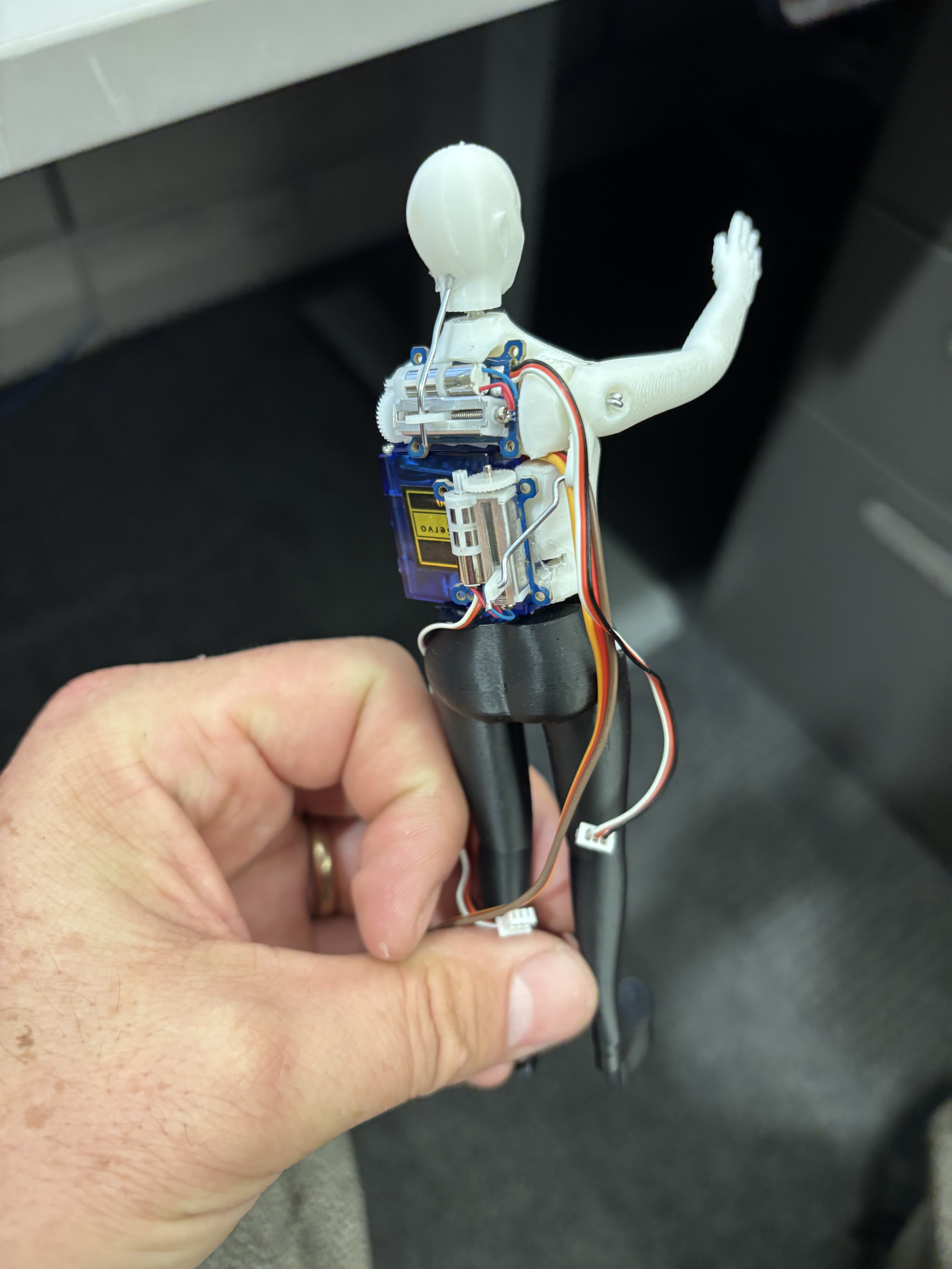
I’m going to use a tiny Arduino compatible controller to move the thing, along with a free program called Bottango to program the animation. (If anyone else is interested in DYI robotics I highly recommend checking out Bottango)
10 Likes
the Jimmy Smits character in Running Scared smuggled coke by turning it into sculptures of saints and “donating” them to the church. this is the Hines/Crystal cop buddy movie, not the other one.
4 Likes
Interesting. I hadn’t heard of that brand before. That is a very large build area. Also, it does look like they’re going to offer an AMS style material changer in the near future, so that’s an option for later.
I placed an order about a week ago for a Prusa Core One kit. I considered waiting and upgrading my current printer, but decided I’d rather keep a working printer while I assemble the new one, and then have two working printers afterwards.
3 Likes
I would love to get a prusa, but 700€ is already too expensive for me (as in… 2/3rds of my salary), 1000+€ is out of the question.
Also the prusa I want is like… 3k€ ![]()
3 Likes
I have a question about 3D printing. I have no current skills with 3D modeling, i did take some 3D modeling classes in college but this was over 10 years ago so… But i am interested in learning 3D printing and potentially buying something affordable to play around with. How difficult is it? Is this something i could learn on my own? Is the software for messing with 3D models free, affordable, or expensive?
Alternatively i have also been interested in laser cutting, though i also don’t know how difficult that would be to learn.
5 Likes
Our local library has a 3D printer and offers classes.
You might check if your local library or community center had something similar.
5 Likes
That depends a lot on how you go about it. There are a lot of free options like Blender, Tinkercad, FreeCAD, etc. I personally lean towards OpenSCAD, but that’s because I’m a weirdo who thinks better in Constructive Solid Geometry and struggle with getting exactly what I want out of more normal modelling software.
8 Likes
It does look like one of the local libraries has an intro to 3D printing but it’s during the work week and its the one library smack dab in the middle of downtown Austin. Which makes it a huge hassle for me, but i’ve bookmarked their classes page to keep an eye on future opportunities.
4 Likes
Nowadays 3D printing is much more accessible than before. If we except the Voron project printers (basically the drag racecars of 3d printing) all printers for sale nowadays are orders of magnitude easier to set up than 10 years ago. If you’re willing to spend some money – and sacrifice a bit of freedom, bambulab offers are almost literally unpack and start printing.
As for modeling there is quite a bit of software catering to many levels. Many of the more accessible and popular ones are web or subscription based, but the open-source offers are getting better. I learned to use freecad from scratch in two weeks just watching YouTube tutorials (I had previous experience with rhinoceros but is a completely different beast). And freecad has improved quite a lot in the. Three years I’ve been using it.
I usually won’t say things like “this is the best moment to start”… But is quite a good moment. Printers are way cheaper, but still not comodditized enough to be feasible to close source them without users raising hell. Improvements are still happening but they are not as dramatic as five years ago (printers are getting faster, but not 400-1000% faster, print quality is better but nowadays improvement has a lot to do with materials, so everyone benefits, etc)
8 Likes
YouTube has a lot of good channels but I will have to post them tomorrow. Not getting out of bed to compile a list of resources ![]()
5 Likes
It wasn’t a decision I took lightly, but my current printer has been busy almost constantly, and my backlog only seems to be growing, so effectively doubling my output was something I could justify. I mostly like Prusa as a company, similar to Framework, so it didn’t make sense to me to shop around. With a different set of constraints, I’d probably make different choices.
The XL is very cool. If I was running a commercial print farm, I think I could maybe justify having one or more of them, but when you can get 3-5 MK4S or Core Ones for the same price, it just doesn’t make sense. So far I haven’t run into anything that the build volume of my current printer has been a hindrance for, but there are obviously specialized situations where it would be useful.
I think if you want to create more artistic or organic models, then Blender is a good choice for that type of work. There are lots of tutorials with many different specialties, many of them free. On the commercial side, I’ve seen reference to ZBrush, but I can only imagine choosing that if you were doing commercial work and could justify the price ($400/year).
If you’re trying to create functional or mechanical models, then a CAD program is probably more reasonable. I haven’t used Tinkercad, but it looks very beginner friendly, and is from a company(Autodesk) with a long history in the space. Their other popular offering is Fusion (360?) which is much more professional focused. It’s also subscription software, and very expensive in my opinion. There is a non-commercial license available for free as well. I have used it briefly to customize a few models, but didn’t find it particularly well suited for that purpose, although part of my problems were due to me struggling (and mostly failing) to get it running on Linux. Some of the YouTube channels I watch seem to prefer Solidworks, but I include it here mostly for completeness. I’m sure there are others.
The three that I’ve used for this purpose are as follows:
Here’s a (not very) brief overview of the process of creating my first (and so far only) 3D printed thing from scratch.
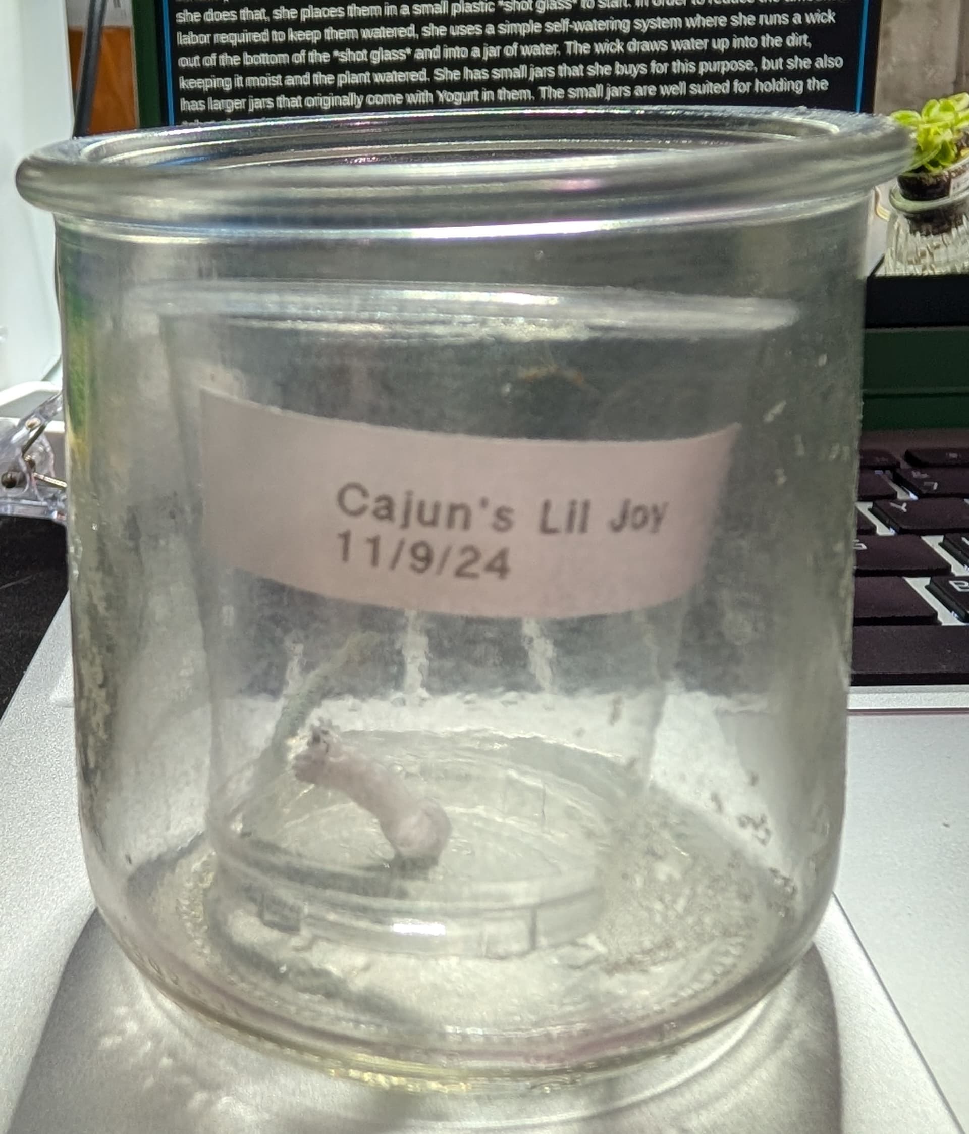
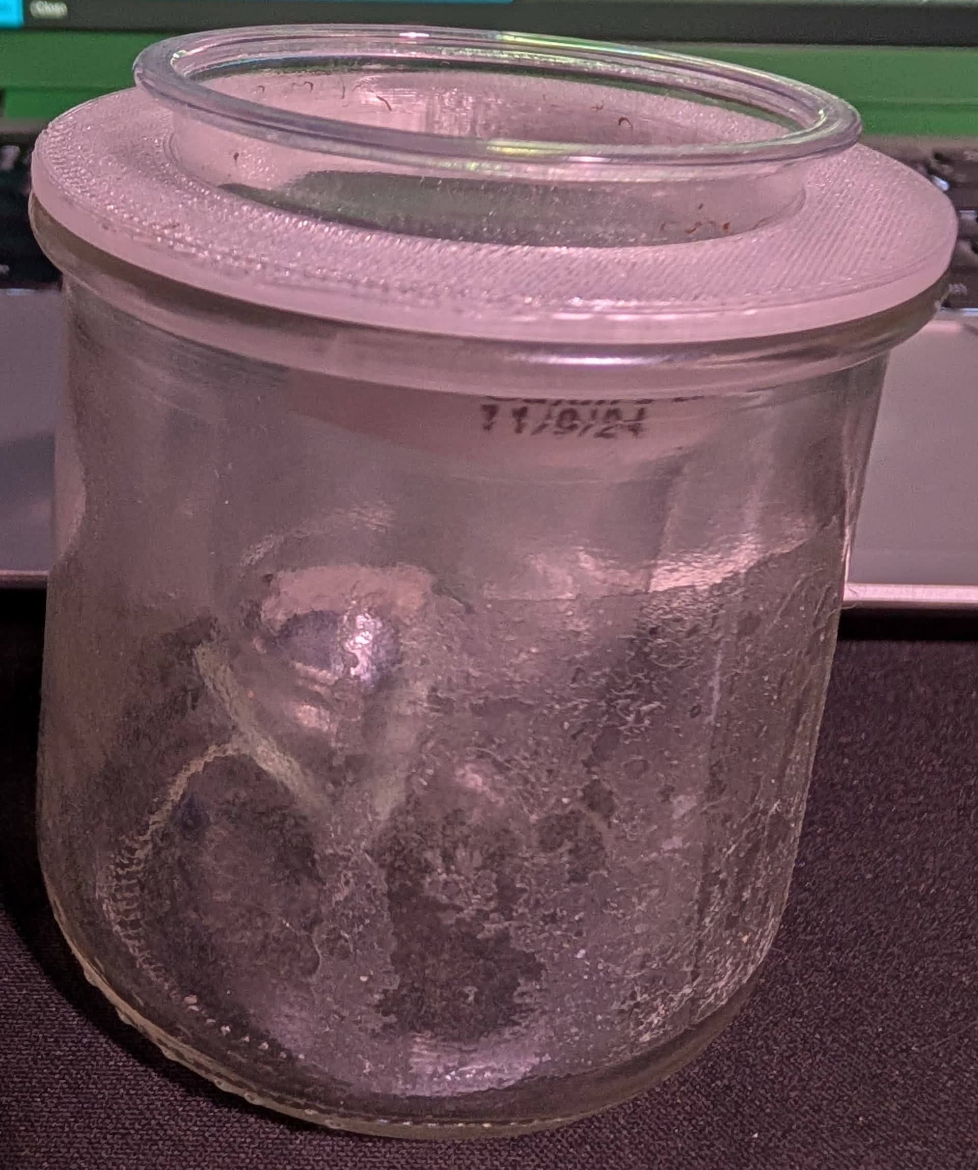
My wife grows African Violets. She grows a lot of them. I think she may have over 200 of them at the moment. Once a plant grows past a certain point, she is sometimes able to take a part of that plant and use it to create a new plant. When she does that, she places them in a small plastic shot glass to start. In order to reduce the amount of labor required to keep them watered, she uses a simple self-watering system where she runs a wick out of the bottom of the shot glass and into a jar of water. The wick draws water up into the dirt, keeping it moist and the plant watered. She has small jars that she buys for this purpose, but she also has larger jars that originally come with Yogurt in them. The small jars are well suited for holding the shot glass in place above the water, but the large jars are not.
Here’s what they look like:
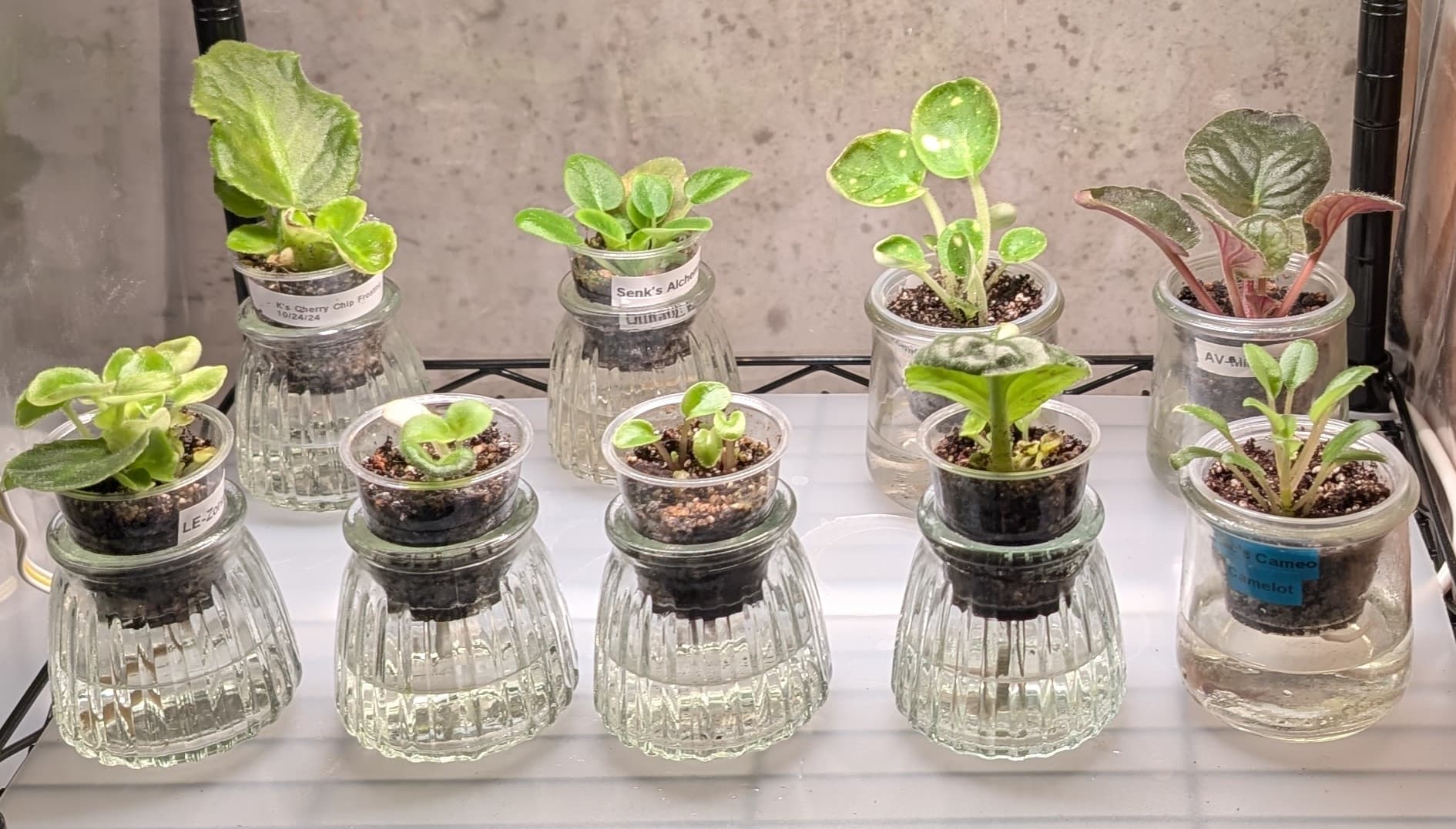
The four starting from the left in front and the two starting from the left in back are in the aforementioned small jars, and the remaining three are in the larger jars. It’s not an illusion, the plants in the larger jars are also in larger cups, which you can see are barely larger than the rim of the jar at the top, which also limits how much water can be stored below. The small shot glass cups don’t fit in the larger jars at all:
Or rather, the fit completely, which makes the jar unsuitable as a water reservoir for that size cup.
All of this is to say that I have a 3D printer, so I should be able to print something to solve this! It should be a fairly straightforward solution, I just need a disc that sits on the rim of the jar, and has a hole in it which is large enough to hold the small cup above the water. Because I am also a weirdo and have effectively zero 3D modelling experience but can write code, my first attempts are in OpenSCAD.
Here’s the code the generates the jar adapter:
difference() {
    union() {
        lid();
        insert();
    }
    hole();
}
module lid() {
    translate([0,0,5]){
    color("Green") cylinder(5,33,33, center = true);
    }
}

module insert() {
    color("Blue") cylinder(5,27.5, 27.5, center = true);
}

module hole() {
    translate([0,0,0]){
     color("Black") cylinder(20, 22.5, 22.5, center = true);
    }
}
That ~22 lines of code generates this model:
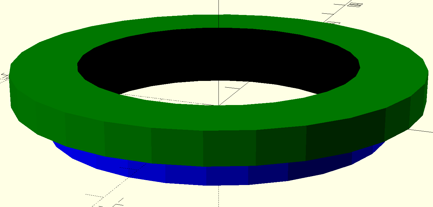
It’s three cylinders: one for the lid (in green), one for the insert (in blue), and then one for the hole through both of them (in black).
Exporting that model as an STL and then slicing it and printing it(upside down) produces this:
After tweaking the infill and print settings a bit, I get it down to ~8g of filament and printing in ~30m on my then MK3S (~15m on my upgraded MK3.9S).
Pros:
- It works.
- I made it with code.
- It’s relatively easy to modify.
Cons: - It’s not perfectly round.
- It may not be obvious in the photo, but it should be clear in the screenshot that it is faceted. It’s not a printing issue, but rather how OpenSCAD seems to generate cylinders by default.
- The workflow of modifying the code, generating the model, exporting it to STL, then slicing and printing it isn’t as smooth as I’d like it to be.
Sometime later, while I was working on printing planters, I started working with some of the basic modelling features of PrusaSlicer, and realized that I could probably generate this adapter directly in the slicer, no OpenSCAD necessary. So that’s what I did.
Using a similar setup with two cylinders stacked on top of each other, and then a negative volume cylinder to make a hole in them, I created this:
It’s functionally identical to the first one, but rounder and smoother.
I went through a few more iterations:
I tried reducing the height of both the lid and the insert, but that ended up with an adapter that didn’t have as good of a grip, so I finally settled on this:
This version keeps the thin lid, but restores a deeper insert so that it grips the inside of the jar effectively. With similar print and infill settings to the first version, it can print in under 10m with ~6g of filament.
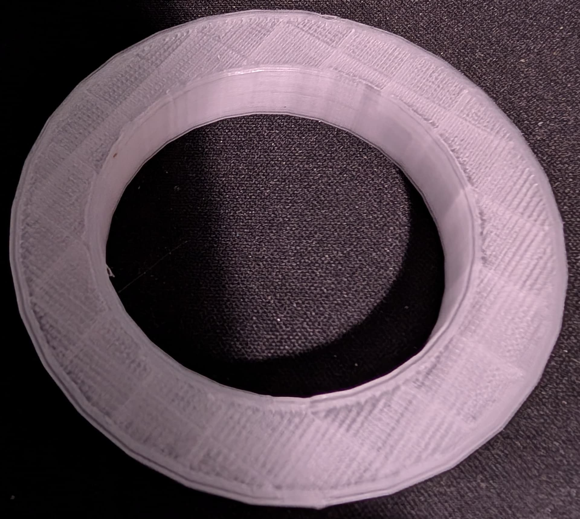
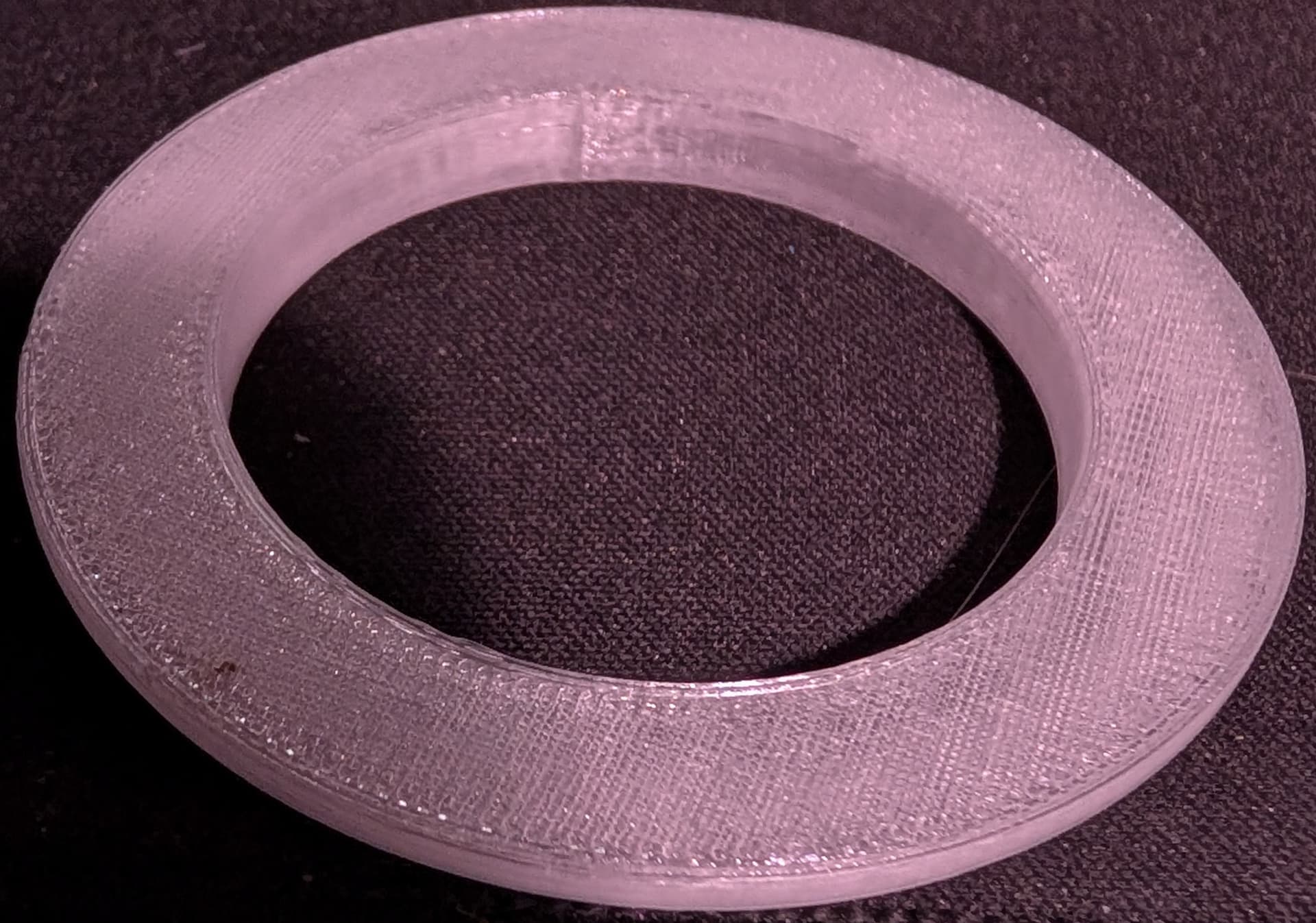
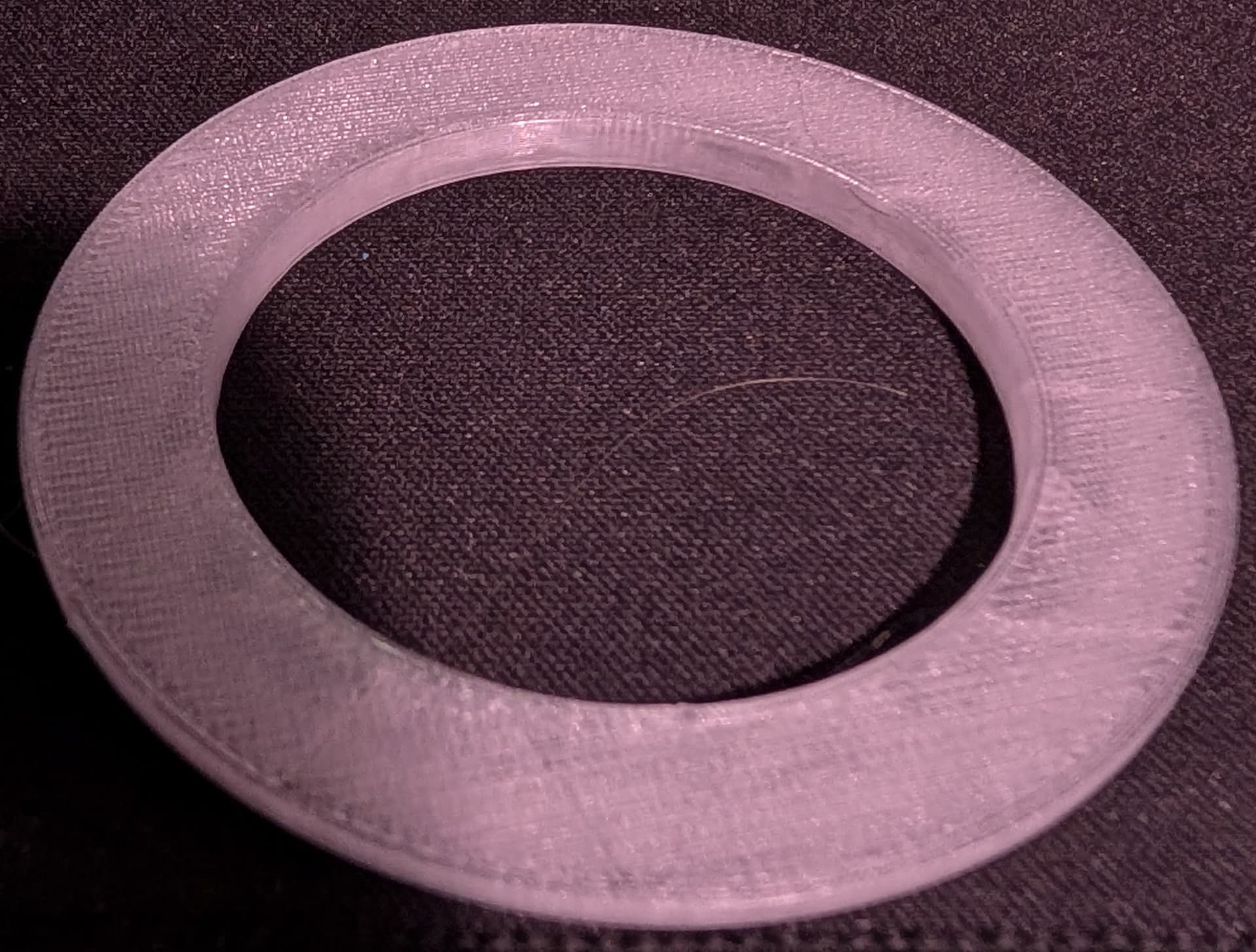
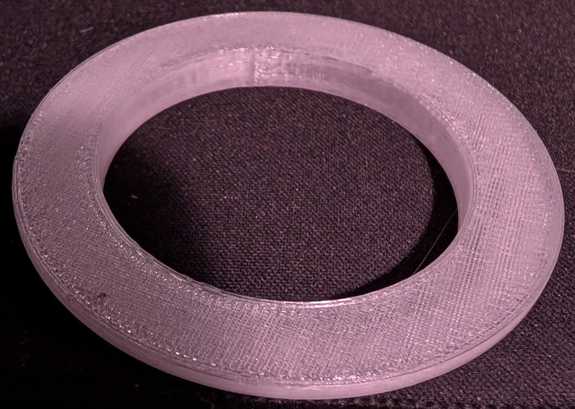
Here’s what it looks like in action:
Pros:
- Easy to modify.
- Rounder.
- Uses less filament.
- Prints faster
Cons: - Less precise editing.
- Not universally shareable.
I’ve been spending a little bit of time learning FreeCAD lately, so I think I’ll try my hand at recreating this again and seeing the advantages and disadvantages of that approach. I’ll report back on that later.
It’s also worth looking into maker/hackerspaces in the area. Here’s a quick search that turned up three around Austin:
https://makerspacedir.com/?select=&lp_s_loc=austin%2C+tx&lp_s_tag=&lp_s_cat=&s=home&post_type=listing
7 Likes
Wierdos unite! ![]()
Honestly, I think the main reason I lean that way is because my earliest 3d modelling experience was with POV-ray, which was a similar thought process. I was also working with more normal (and much more expensive) cad software for drafting at the time, but haven’t quite connected the processes…
Which may be to say, it’s worth it to try several of them and do some tutorials, with an eye towards an engaging project.
4 Likes
On freecad the process would be like this
(Optional) Step 0: Write down the measures
So, this can be skipped if you think you won’t need to tweak the piece a lot, or is a one-off, but one of the nifty features of FreeCAD is that, as the models are based on plans, you can commit some of the plans measures into a spreadsheet. As I’m not sure of the measures you use, I’ll do that.
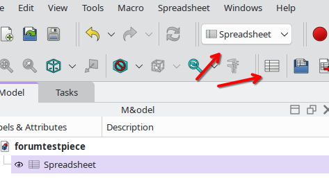
I select the Spreadsheet “bench”, and click on “new spreadsheet”.
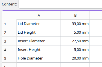
I Input the data. With this we could already use it, but then we need to reference them by Coordinate (as in Spreadsheet.B1).
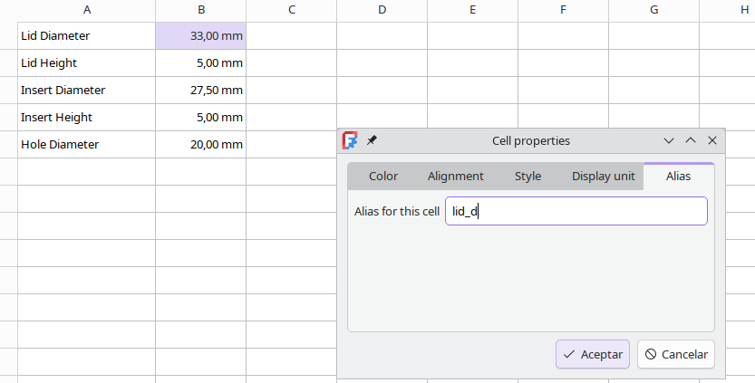
Instead of that, I can right-click on each cell, go to properties and assign an alias. Again, this is not needed, just makes easier to modify the model after.
Step 1: Make the model
FreeCad uses an additive-substractive model that favors pieces that overlap, so I’m going to build this upside down (which is how we are going to print it, anyway). This model will be composed of two cilinder primitives (the lid and insert), and one substractive primitive (the hole). For more complex designs we would have used sketches, but this is not the day ![]()
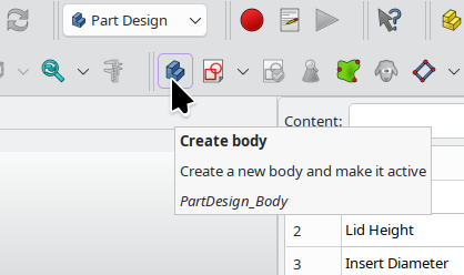
We select the bench “Part Design” (basically the one you’ll be using normally) and click on “Create Body”.
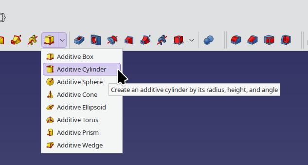
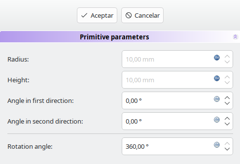
We click on “Additive primitives” and select “Additive Cylinder”
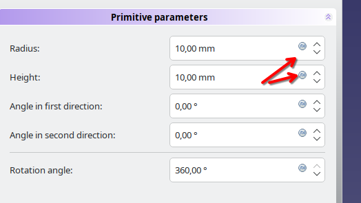
We can input the information directly, but as we saved the data on our spreadsheet, we need to click on the “formula/expression” button.
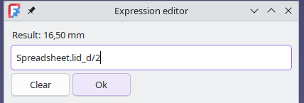
As I wrote it as diameter, but the cilinder generator expects radius, I divide my value in two.
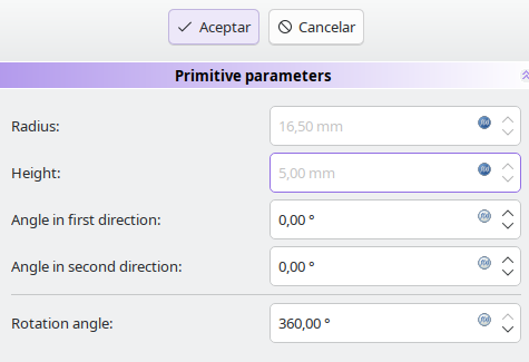
Note that the parameters that are generated using an expression are greyed out so we cannot change them manually from here.
We repeat the process for the second cilinder.
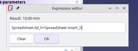
For the insert, as FreeCAD prefers overlapping models, I’m going to generate it from the bottom, but make the height equals to the height of both the lid and the insert.
So far so good.
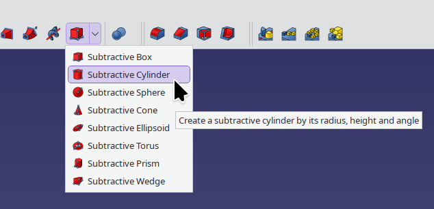
For the hole, we need to click on “substractive primitives” then select “Substractive Cylinder”
The formula for the height is the same as the one used in the insert. If I was doing this manually, I would add some margin in the bottom and the top (like 1mm on both sides) but this should be fine.
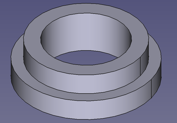
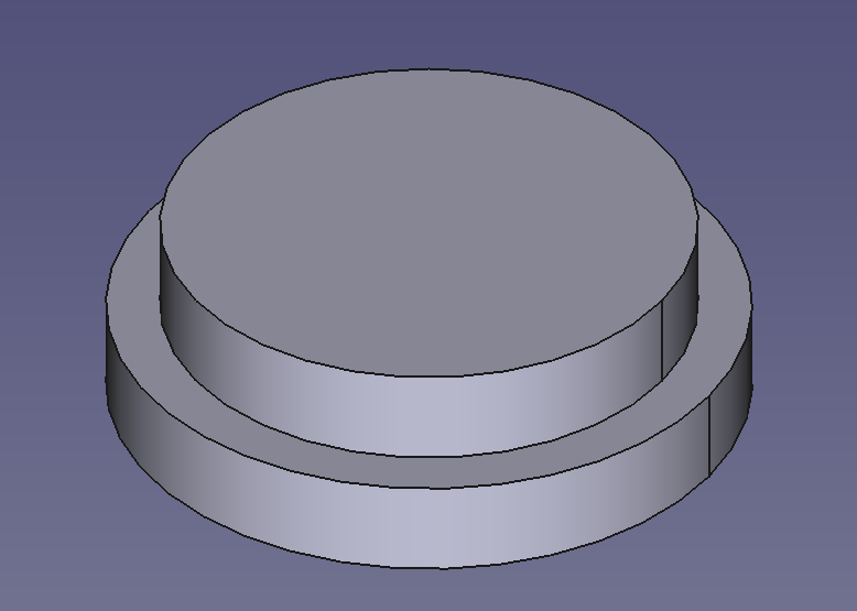
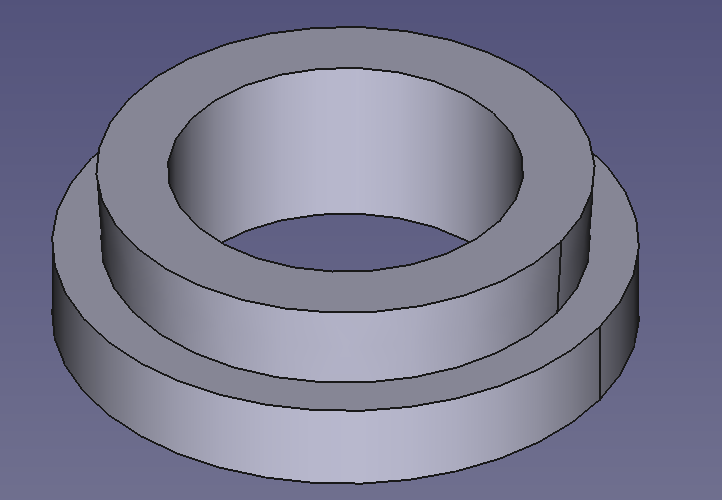
The “finished element”
Step 2 DFM
Here is the part where I usually add some finishing touches using the “Fillet”, “Chamfer”, “Draft” and “Thicken” tools to fine tune the design for printing.
For example, we could add a bit of Draft to the exterior wall so it grips against the wall better, playing with the elastic tolerances of PLA. To do that I click on the exterior wall
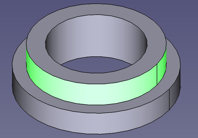
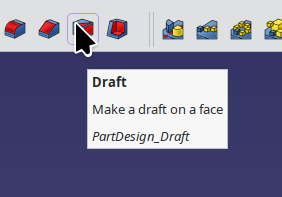
And select “Draft”
FreeCAD is usually good at figuring out the orientation of the wall, but you can click on “Neutral plane” and select the wall you want your draft to grow or reduce against.
Here’s with a draft of 3º.
We also don’t need that much material on the insert --again assuming the insert needs to grip the exterior wall, not the interior – so I’m going to draft the walls to make them thinner towards the bottom (top on the model).
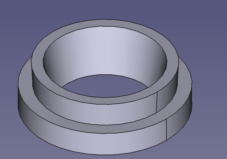
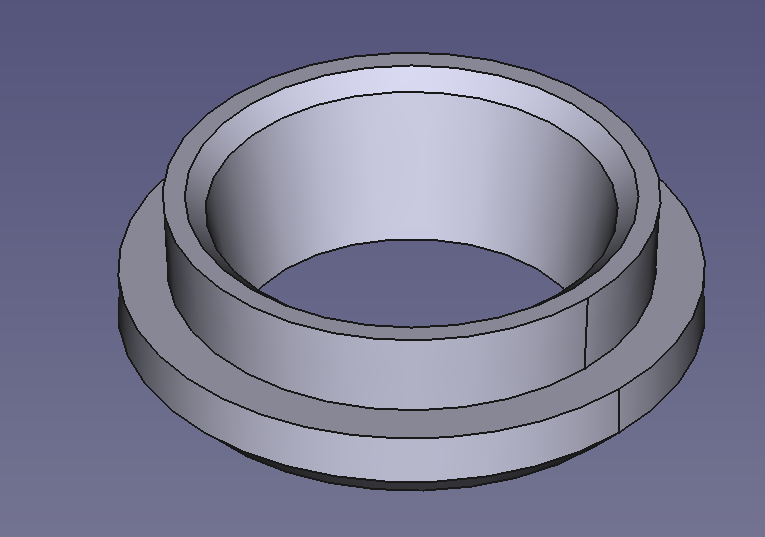
And I’m going to add some (2mm) chamfers on the lid (3D printers are not very good at rounded fillets so is better to keep it 45 degrees if you care about print quality) and the upper part of the insert (1mm).
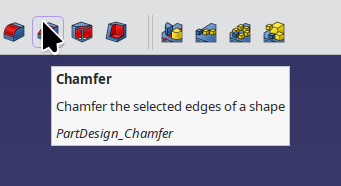
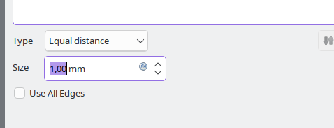
To create a chamfer you select the border between two faces.
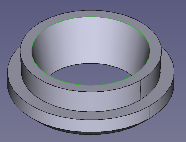
And then click on “Chamfer”
Usually the default “equal distance” is good, and you only need to change the size. but sometimes you want a fillet in an specific angle or of a specific depth, and there are options for that too.
And the finished model, that can be exported into your favourite slicer.
And here you can download the file I made so you can examine, print or modify it at your leisure ![]()
9 Likes